2-D TRUSS DESIGN
(Complete Design Software)By:
S. Kokularamanan
T. G. Suntharavadivel
Supervisor: Prof. M. P. Ranaweera
Project Number: C/2000/119
This project is aimed at developing platform independent, engineering design software that can be loaded through the Internet or down loaded from the worldwide computer networks. These are useful for learning as well as teaching.
Present software module called 2-D TRUSS DESIGNER can be used for analysis and design of any shape of 2-D truss for any given loading conditions. This module has two main parts; an analytical part and a design part. In the analytical part user can analyze and obtain the deflected shape, member forces and support reactions for the truss. In the design part one can select the standard sections for the members to satisfy the design criteria according to BS 5950 Code. Therefore this software covers major portion of the second year structural design. This software has a user-friendly graphical interface.
ACKNOWLEDGEMENTS
It is our pleasure to take this opportunity to thank all those who helped and directed us to finish this project successfully. First of all we sincerely express our gratitude to our project supervisor Prof. M. P. Ranaweera (Department of Civil Engineering) for offering us such a good opportunity to carryout this project under him. His wise guidance, project related materials and continuous encouragement are the main reasons for the success of this achievement.
We extend our thanks to our final year project coordinator Dr. J. J. Wejethunge (Senior Lecturer, Department of Civil Engineering) for giving necessary support and guidance to carryout this project.
It is also our pleasure to express our sincere thanks to Dr. K. R. B. Herath (Senior Lecturer, Department of Civil Engineering) for his support in loading this software to the Internet.
We also wish to thank all other staff and friends who gave support to complete this project in time.
September 2000 S. Kokularamanan
T. G. Suntharavadivel
TABLE OF CONTENTS
1.1 Background
1.2 Aims and objectives
1.3 Scope of work
2.1 Development of Java code
2.2 Previous study
3.1 Brief history of development
3.2 Software development
3.3 Implementation of software
4.1 General
4.2 Analytical part
4.3 Design part
5.1 General
6.1 General
6.2 Difficulties encountered
7.1 Summary
7.2 Conclusions
7.3 Recommendations for further studies
Appendices:
Appendix I: Summary Of Technical Details Of Source Code
A Cross section area (m2 )
a1 Net sectional area of the connected leg (m2 )
a2 Net sectional area of the unconnected leg (m2 )
Ac Effective area (m2 )
Ag Gross cross section area (m2 )
Cd Dead load coefficient ( )
Ci Imposed load coefficient ( )
Clw Leeward load coefficient ( )
Cww Windward load coefficient ( )
d Displacement vector (m )
E Young’s modulus (N/m2)
Fext External force vector (kN )
Ft Design force (kN )
K Structure stiffness matrix (kN/m)
ke Member stiffness matrix (kN/m)
L Length of the member (m )
Pc Compression capacity (kN )
Pt Tension capacity (kN )
pc Compressive strength (N/m2 )
pt Tensile strength (N/m2 )
T Tensile force (N )
W Weight (kN )
Slenderness ratio ( )
Fig. No
. Description Page3.1.1 Applet window at testing site
3.3.1 Typical truss and loading
4.2.1 2-D Pin jointed structure
4.3.1 Equivalent dead load distribution
4.3.2 Equivalent wind load distribution
5.1.1 Main window
5.1.2 Create new file dialog box
5.1.3 Add nodes dialog box
5.1.4 Graphical input of nodes
5.1.5 Add/change members dialog box
5.1.6 Display of input data graphically and tabular form
5.1.7 Modify or add restraints dialog box
5.1.8 Graphical display of the loading arrangement
5.1.9 Automated load combination dialog box
5.1.12 Display of the member check results
1. INTRODUCTION
1.1 Background
Most important activity in engineering is design and optimization. To get the optimum design it is necessary to try different inputs. To do this manually is time consuming and sometimes impossible. By using computers, the optimum can be achieved very easily as well as quickly. For this purpose several packages are available in the market. But there are very few packages that can be loaded in Internet[1]. This project is aimed at developing an Internet accessible module for design of 2-D trusses.
In early 1970s many software packages for civil engineering problems were written in Fortran 77 without much user interfaces. After that there came Basic. After the introduction of 'C' language by Bell labs in 1980’s[2] software development took a new path. However in the field of civil engineering software packages did not take the advantage of C language even in the 1990’s. For example popular finite element package SAP 90 was actually written in Fortran. Even its current version SAP 2000 contains fairly large amount of Visual Basic code. Same story applies for Java [3] and Internet also. However in the former case, it did not matter much, as very fast computers were evolving and accuracy of these older programming languages was also good enough. However as regards the Java and Internet it is a different story since, there may not be any desktop computers in the future as net-based computers are evolving very rapidly. Sun Microsystems president Zagner says "I believe most of the population throughout the world will not be using PC to get into the Net in a few years time. They will use wireless type devices to get on the Internet"[4]. These computers do not even have hard disks where the conventional programs reside and loaded to memory as they are executed.
In our University in past years some analytical software were developed for the Internet and some design software were also developed for simple problems using Java [5]. But this is the first time design software is developed for the Internet incorporating finite element analyses, graphical inputs and design codes.
1.2
Aims and ObjectivesWe concentrated on developing a very user-friendly module, which will enable even a novice user to use it without much effort to learn it. Furthermore, in order to facilitate second year design class students, an export import facility also was incorporated into the Application module. In this exchange utility student will be able to exchange Pin[8] created data files to and fro. That eliminates our University's dependant on freeware program by another university and allows future modification according to our needs. In order to facilitate this project entire source code will be made public. In addition to this, technical explanations for, (with regard to structural and programming) most important areas, were provided in this report. That will enable third and final year students to visualize the implementation of Finite element method in computer more clearly and practically. This will enhance their knowledge in structural engineering, and will give them the confidence to program computers to solve any kind civil engineering problems. This obvious fact we have seen during our project time even. After seeing demonstration of our software and using our module (after some of the technical guidance), some of our friends were able to program nice modules for stress-strain analysis.
Another target is to utilize information superhighway in a relatively new way, that is Internet to civil engineering analysis and design. It should be noted that, it is a significantly new idea to introduce design capable applets on the net. Further more modern technologies like WAP (Wireless application protocol) may enable the use of Internet to computation more seamless in the future.
In addition to this, this module functions as a very simple and efficient tool for designers also. Considering above three types of audience, we aimed to cover wide range of audience also. Through the platform independence nature of Java, a user with Macintosh or Apple machine will be able to use this same module with same GUI and functionality without any problem. Thus almost anyone with browser will be able to use this module.
1.3 Scope of the work
Using Visual café 3.0 (under laying of JDK version 1.1.7) a module for the complete design of pin-jointed frames was developed. This module/modules were specially verified for truss design according second year design class requirement. BS5950 part 1 requirement for the steel structures were covered fully. Detailed discussion of this was mentioned in the chapter dealing with theory. For the applet module HTML 4.0 was used to decorate the web pages and online help files. For the demo PowerPoint 97 was used.
2. LITERATURE REVIEW
2.1 Development of Java code
During past two decades many programming languages evolved. However only some are truly object oriented, a revolutionary concept introduced by Smalltalk and powerfully implemented by C++. Based on C++ relatively new language called Java was introduced in 1995, with many unique features, which made it very famous among the software development communities within a very short time.
Following are special characteristics of Java:
Although Java has several advantages over the other languages, it also has some demerits, such as:
For the GUI development Sap 2000 was taken as modal. Especially frame analysis features of Sap 2000 GUI followed in order to make it easier for Sap 2000 user. Other than this standard commercial software’s feature like database handling and file dialog boxes and file saving features were implemented. Zooming and panning facilities were implemented much like AutoCAD.
2.2 Previous study
University of Sheffield developed similar package modules previously about 8 years ago, which can run on MS-DOS. Later another package called Microfeap by AIT (Asian institute of technology) was also developed. In this module, design capability and much more user-friendly features were incorporated.
3. METHODOLOGY
3.1 Brief History of Development
At the initial stage analysis part of the software was done. At this stage we realised that file handling was necessary, and with limited file handling feature we were able to produce an applet as shown below.
Fig.3.1.1 Applet Window At Testing Site
Above module was available at our testing site www.members.tripod.com/truss_designer. Since then working on Design capability was started. At this stage necessity of application was realised, due to file handling problems. Then previous applet was converted into application and standard file handling features were implemented for the data input files. During the conversion the GUI appearance was also completely changed in order to facilitate design of fairly complex and large structures. Similarly section database file was also implemented. Afterwards complexities in the loading combinations were taken into account. After finishing required features this application was converted into the applet, after modifying the file handling parts little bit. Now it is available in two flavors as Java application and applet. Here after when module was mentioned it refers to both application and applet. To check the results of this module Pin package was used.
3.2 Software development
Java virtual machine and standard libraries have changed a lot since its first release on 1995. JDK 1.0.2 was initially used and then entire code was converted to event delegation model and used JDK 1.1.7 at last. Although JDK 1.2.2 was already released it was not used in order to maintain the compatibility issues. Initial development was done in Visual café 1.0,installed in a 486DX4 machine and then at the latter parts Visual café 3.0 was used on AMD K6-2 500 with 64MB ram. But even this new AMD K6-2 500 also barely satisfied the memory requirement of Visual cafe3.0.
In this module standard sectional properties database is available. This database is based on sections available through State Steel Corporation of Sri Lanka. And also user can extend this if he wants to do so. This database is available as "sections.dbt" ASCII file. This module has 14 Java files. Although these can be put into a single file, they are actually made into 14 files for the following reasons.
Files involved in this part are,
1. PinApp.java : Main module integrates other procedures in the other java class files. In the application module this is the startup class.
2. AboutDialog.java : Displays the information about the software module
3. CreateDia.java : Code required for creation of new dialog box.
4. FrceComFrm.java : Code for force combination dialog box.
5. MemProFrm.java : Code for the display of member properties and the sectional database display.
6. NodeFrm.java : Dialog box for nodal details/information.
7. ResFrm.java : Restraints or force display dialog box.
8. QuitDialog.java : Dialog box to ensure the termination of the module
9. GlobalSystem.java : To form global matrix
10.TrussRun.java : Main applet.
11.ViewPanel.java : Creates the panel with many visual enhancement for display of the structure
12.Element.java : Processes the element details.
13.WarningDia.java : Displays the warning messages when it was necessary.
14.Matrix.java : Processes the matrix operations. This module can be used for other matrix related engineering problems.
These modules can be categorized into 2 main types according to their functions. They are;
These modules handle calculation-oriented parts like stiffness matrix formulation, finding the inverse matrix etc. Element.java, GlobalSystem.java are these files.
These modules are mainly for graphical user interface (GUI). All the other modules except the above-mentioned come under this category. However some of these serve as both computational and interface modules. PinApp.java and FrceComFrm.java are good examples for these kinds of modules.
3.3 Implementation of the software
In the initial stage, 2-D truss of any shape can be analysed. After the analysis, user can select the suitable member sections for the truss.
In the analysis part the displacements, axial forces and support reactions of the truss are found. This analysis is based on the finite element displacement method[6].
This analysis is done in three different stages as follows;
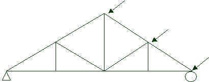
Current module can be used to analyze and design a 2-D Truss of any shape under loading such as concentrated loads at joints as well as distributed loads under any support condition.
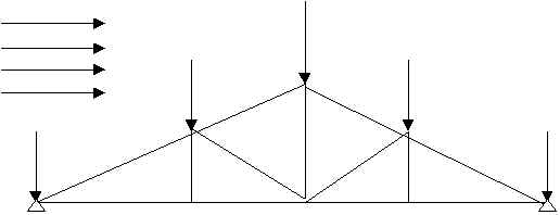
Fig.3.3.1 Typical truss and loading
The geometry of the truss, its loading and support conditions can be input graphically or by tabulation. Once the problem is defined, the analysis is done using the finite element method [6] and design of members is done in accordance with the BS Code of Practice [7].
3.3.1 Pre processing stage
The PinApp.java file is involved with this stage and this is the main module involved in the analysis and design part. It starts application as necessary. It enables the user to input data graphically or alpha numerically.
The main steps involved in the structural data input stage are,
ø Define the number of nodes, members.
This is necessary to create the global stiffness matrix. Scale of the structure also can be selected here.
ø Define the nodal co-ordinates.
In this step user can define the nodal coordinates by using either keyboard or mouse.
ø Define the members.
In this step user can define the member connectivity and properties. Here user can select the member designation from the database. In addition to that user has to give Young’s modulus, yield strength and slenderness ratio coefficient of the member. If user does not change the default values in the text box it will automatically take that default value.
ø Define the boundary conditions and the nodal forces.
In this step user has to define the restraints of the nodes and the nodal forces. If the user wants to do design of standard truss geometry, he can use automated loading facilities in this software.
3.3.2 Processing stage
This stage involves the following steps.
ø Form the member stiffness matrix and then position it in the structure stiffness matrix.
ø According to the boundary condition reduce the size of the structure stiffness matrix (striking off)
ø Solve the reduced stiffness relation for the unknown displacements.
ø By using these displacements form entire displacement vector, and find all the external forces.
ø Using these results member forces are evaluated.
ø Check the members for their tension and compression capacities.
3.3.3 Post processing stage
This stage includes the following steps.
ø Graphical and numerical output of the deflected shape of the structure.
ø Numerical display of the member forces.
ø Results of the member capacity checks.
If failure of a member occurs user can change the member properties and return to do the processing and post processing again.
4. THEORY
4.1 GENERAL
This 2-D TRUSS DESIGNER software consists of two main parts,
1. Analytical part
2. Design part
The analytical part is developed based on the finite element displacement method, and the design part is based on the BS 5950: Part I 1990[7].
4.2 ANALYTICAL PART
In the analytical part, the member forces and the nodal displacements are calculated. By using this analytical part any 2-D pin jointed structures can be analyzed under any loading conditions. However in this software some special features are available for the design part process.
To describe the theory, consider the following 2-D pin jointed structure.
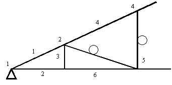
Fig.4.2.1 2-D Pin jointed structure
4.2.1 Formation of the member stiffness matrix.
Consider the first member of the structure.
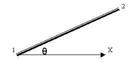
Fig.4.2.2 Member section
Data: Nodal coordinates (X1, Y1) and (X2, Y2)
Area of the cross section (A)
Young’s Module (E)Then the member stiffness matrix is given by,
Where,
L= {(X1-X2)2+(Y1-Y2)2}1/2
C=Cos ? =(X2-X1)/L
S=Sin ? =( Y1-Y2)/L
4.2.2 Formation of the structure stiffness matrix.
Data: Number of nodes (n)
For the member 1, the position in the structure matrix is <1,2,3,4>. In the case of a general member having the nodal numbers i and j, the position is <2i-1, 2i, 2j-1, 2j>.
In this software, initially the structure stiffness matrix is formed as a (2n x 2n) zero matrix (null matrix). Then each member matrixes is added to their corresponding positions. Finally this ends up with a (2n x 2n) structure stiffness matrix K.
4.2.3 Formation of Displacement vector and Force vector.
The displacement vector is a column matrix, which is given by,
From the restrain data, the boundary conditions can be defined. (Some of the displacements are known.)
Example: If the joint 1 is pin support, then d1X=d1Y=0
If the joint 3 is roller support (in X-direction), then d3Y=0
The force vector also a column matrix, which is given by,
Similarly from the restraint/ force dialog box particular force components of above matrix are computed from prescribed loads. An automated facility for applying standard loading is described in section 4.3.2.
4.2.4 Solving the equations.
From the above steps, all three matrixes of the equation K.d=Fext are defined.
First this equation is solved for displacement. To solve this equation for displacement, strike off method is used. That is if a displacement is zero, the corresponding row and column in the structure stiffness matrix is strike out.
Example: If the 6th element of the displacement vector (d3Y) is zero, then the 6th row and column in the stiffness matrix are strike out.
Then the remaining part of the equation is k.d1=fext. Using LU decomposition k-1 will be found. Then this equation can be solved for d1. That is all the nodal displacements are calculated.
4.2.5 Calculation of the member force.
To find the member forces the following equation is used. (Tension is taken as positive.)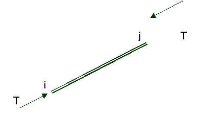
Fig.4.2.3 Member forces act in a member
At the end of the analysis part the following results are calculated and displayed in the screen.
4.3 DESIGN PART
For design calculations, the analytical part has the following features in addition to its general features.
4.3.1 Member selection
The user can select the angle section from the database. If user wants to give a different section he can add that section in the database.
4.3.2 Automated load combination facility
For 2-D truss design, generally the following loading conditions are considered.
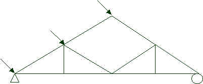
a. Dead load
Dead loads act vertically. So the distributed loads on the member can be represented as follows,
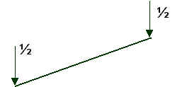
Fig.4.3.1 Equivalent dead load distribution
b. Imposed load
Imposed loads also act vertically. So its distribution also can be considered similar to the dead load.
c. Wind load
Wind loads act perpendicular to the members. So it can be equated as follows,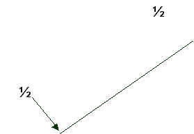
Fig.4.3.2 Equivalent wind load distribution
So, finally the module automatically analyses the following loading arrangements,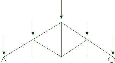
a. Dead load and Imposed load
b. Windward load
c. Leeward load
Fig.4.3.3 Different loading arrangements
Then the module will tabulate the member forces for the above three arrangements as F1, F2 and F3 respectively.
According to the BS 5950 Part I: 1990[7], the following loading combinations are considered in the module.
1. 1.4 F1*Cd + 1.6 F1*Ci
2. 1.0 F1*Cd + 1.4 (F2*Cww+ F3*Clw)
3. 1.0 F1*Cd + 1.4(F2*Clw +F3*Cww)
4. 1.2 (F1*Cd + F1*Ci + F2*Cww + F3*Clw)
5. 1.2 (F1*Cd
+ F1*Ci + F2*Clw + F3*Cww)Among the above five combinations the maximum value (in magnitude) is taken as the design force. In the module the load coefficients are given as input data. These coefficients are depends on the location (wind speed, snow), materials that used for covering, ceiling and purlins and slope of the roof. The brief method to calculate these coefficients is given below,
a. Calculation of Dead Load Coefficient (Cd)
Dead loads are,
Weight of the roof covering = w1 N/mm2 (slope area)
Weight of the ceiling = w2 N/mm2 (plan area)
Weight of purlins = w3 N/mm2
Weight of roof truss = w4 N/mm2 (plan area)
Then,
Cd =w1*A+w2*A Cosa +w3*l+w4*A Cosa
b. Calculation of Imposed Load Coefficient (Ci)[9]
The imposed loads, including snow load, on roofs with a slope greater than 100 where no access is provided to the roof (other than that necessary for cleaning and repair), are as follows,
Note: A reduction of 0.25 kN/m2 may be made for snow loads in area where there are no snowfalls.
c. Calculation of Wind Load Coefficient (Cww & Clw)[10]
Dynamic pressure of the wind, q= 0.613 VS2 N/m2
And VS= VS1S2S3
Where,
V Basic wind speed.
VS Design wind speed.S1 Multiplying factor relating to topology.
S2 Multiplying factor relating height above ground and wind breaking.
S3 Multiplying factor relating to life of the structure.
Pressure at any element of the structure, p= (Cpe-Cpi) q N/m2
Where,
Cpe Pressure coefficient for external surface
Cpi Pressure coefficient for internal surface
These coefficients can take from the CP3.
If the user wants to give a different loading arrangement or different loading combinations other than the standard loading feature, he/she can skip this facility and can follow the general procedure as in the analytical part. Then he/she should enter the design forces for each member as input data in force combination dialog box as mentioned in the online help.
4.3.3 Design checks
Then the software checks whether the selected member sections are adequate or not for the following checks.
a. Check for simple tension members[7]
Clause 4.6.1 of the code state that the tensile capacity Pt of a member should be taken as,
Pt= Ac X py
Where, Ac is the effective area, it can be calculated as follows,
Ac= a1+ k*a2
And k=3a1/(3a1+a2)
Ac= a1+ k*a2
And k=5a1/(5a1+a2)
Then check Ft = Pt
And calculate factor of safety, FOS=(Pt/Ft)
b. Check for simple compression members[7]
Clause 4.7.4 of the code state that the compression capacity Pc of a member should be taken as,Pc= Ac X pc
Where,
Ac is the effective area, it can calculate similar to the tension check.
pc is the compressive strength of the member. It can be taken from table 27(c) of the code or using the equation,
Then check Fc= Pc
And calculate factor of safety, FOS=(Pc/Fc)
At the final stage the software gives the following results,
1. The check OK or NOT.
2. The factor of safety.
If a member fails, the user can change the section and can check again.
CHAPTER 6
6. WORK SCHEDULE
6.1 General
During the 20 weeks we were able to follow the work schedule as we proposed earlier (Table.1). Although we finished the analytical part before the expected time, the design part took much more time than our proposed period. However the all works were finished within the period of 20 weeks.
6.2 Difficulties Encountered
Although we have tried several browser versions (IE 4.0,5.0, Netscape 4.5,4.57) there are some problems with some machines. We think it must be because of the installation problems. In other words sometimes some run time libraries (Dynamic link library files) may be corrupte and the browser will show some peculiar behaviors at some particular instances. Furthermore Microsoft Internet Explorer does not have the full Java support as the Netscape in order to promote ActiveX. However Netscape browser is not widely available like the Internet Explorer, became latter is available as freeware.
Another main problem was the JVM (Java virtual machine’s) security manager. It controls and executes the entire Java byte code after it verifies the byte code. Within the applet context it was not possible to write files or load standard file handling dialog boxes with electronic signature. This electronic signature concept was little bit confusing for novice users. Therefore file-handling part was eliminated in the applet version of this software module. However file saving and reading can be done by direct user intervention as mentioned in the online helps and in the PowerPoint demo.
7. CONCLUSION
7.1 Summary
In this project pin jointed structural analysis and complete design software modules were developed in Java. They are available in two flavors, and are platform independent.
7.2 Conclusions
Engineering design involves lot of repeated calculations (what if analyses). Although this can be managed by manual methods for small structures, for large structures its very time consuming and results are error prone. Therefore computer software with user-friendly features and foolproof algorithms are very important in modern engineering designs. The software developed under this project is user friendly and platform independent and hence can be used by anyone, who was involved in learning, teaching or design process using any machine and from anywhere.
7.3 Recommendations for further studies
This project was only concerned with 2D-Pinjointed structures. It can be extended to 2D rigid-jointed structures, which can be utilized by third year design students. It will require only small modification to this module in the core code and the database.
REFERENCES